

You can easily wire this breakout to any microcontroller as long as you have 3 available analogue ports. We’ll be using an Arduino.
The accelerometer module has ratiometric analog voltage outputs, in other words the output of the module is an analog voltage proportional to the acceleration in the corresponding axis. The following pins should be used:
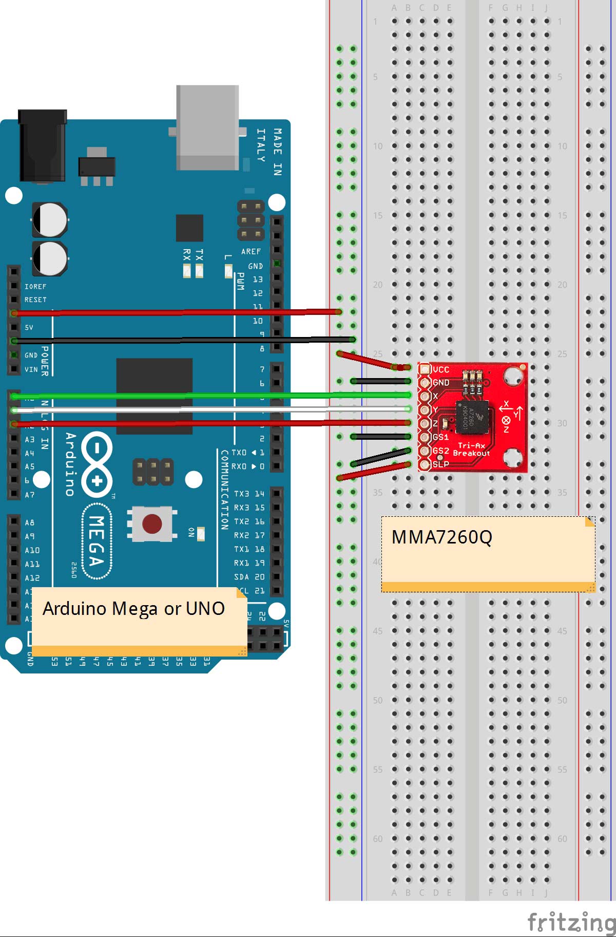
- Connect Vin to the 3.3V power supply.
- Connect GND to common power/data ground
- Connect X pin to the analog pin A0
- Connect Y pin to the analog pin A1
- Connect Z pin to the analog pin A2
- Connect GS1 and GS2 to ground
- And the Sleep pin to 3.3V. If you want to minimize the power consumption you can use a digital output pin toggle the sleep mode function
To begin reading sensor data, you can just run a analogRead command but what you will get is a value, let’s say X, between 0 and 1023 thanks to the Analog to Digital Converter. This value corresponds to X*5/1023 Volts.
As we said in the previous page a negative acceleration will result in a value from 0 to 1.65V and a positive one will be something greater than 1.65V. In order to use these analog values we need to know where the zero bias point is. (Usually around half of his supply voltage) So let’s calibrate the sensor to determine a reliable reference point for our measurements.
Calibration
int N = 50;

float zeroPoint(int axis)
{
 float acc = 0;
 for (int j=0;j<N;j++)
 {
   acc = acc + (((float) analogRead(axis)*5000)/1023.0);
   delay(20);
 }
 return acc/N;
}
With the range setting chosen at +/-1.5g and 800mV/G of resolution, the value of acceleration can be obtained with the following formula:
In order to improve the sampling rate we will set up a few timers to keep track of the time interval between successive readings. Upload the following sketch.
const float RESOLUTION=800; // Resolution 1.5g -> 800mV/g
const float VOLTAGE=3.3;
const float ZOUT_1G = 850;   // mv Voltage @ 1G
const int N  = 50;

// Connect the X,Y and Z pin to A0,A1 and A2 respectively
const int xaxis = 0;
const int yaxis = 1;
const int zaxis = 2;

float zeroX,zeroY,zeroZ;
int x,y,z;
float aax,aay,aaz;

// Acc Timers
unsigned long accTimer;
unsigned long lastAccTimer;

byte mode;

#define DEBUG

float zeroPoint(int axis)
{
 float acc = 0;
 for (int j=0;j<N;j++)
 {
   acc = acc + (((float) analogRead(axis)*5000)/1023.0);
   delay(20);
 }
 return acc/N;
}

void setup()
{
 Serial.begin(9600);
 pinMode(xaxis,INPUT);
 pinMode(yaxis,INPUT);
 pinMode(zaxis,INPUT);

 zeroX =  zeroPoint(xaxis);
 zeroY =  zeroPoint(yaxis);
 zeroZ =  zeroPoint(zaxis);
 zeroZ = zeroZ - ZOUT_1G;
}

void loop()
{
 accRoutine();
 delay(20);
}

void accRoutine()
{
   x=analogRead(xaxis);
   y=analogRead(yaxis);
   z=analogRead(zaxis);

   aax = (((x*5000.0)/1023.0)-zeroX)/RESOLUTION;
   aay = (((y*5000.0)/1023.0)-zeroY)/RESOLUTION;
   aaz = (((z*5000.0)/1023.0)-zeroZ)/RESOLUTION;

   // computes sample time
   accTimer = millis() - lastAccTimer;
   // updates last reading timer
   lastAccTimer = millis();

    #ifdef DEBUG
     Serial.print("Acc
Try tilting the sensor and check if the acceleration along the x and y axis change. Your serial monitor should look like this:
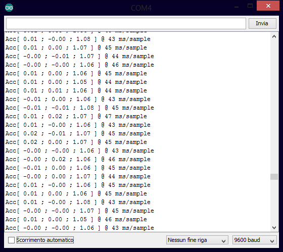
In the next page we will speed up the readings using different approaches.