

In the first part of this section we will see the basic circuit and get the raw data. In the second we will calibrate the sensor and get the acceleration in g or in SI units if you want.
Arduino wiring
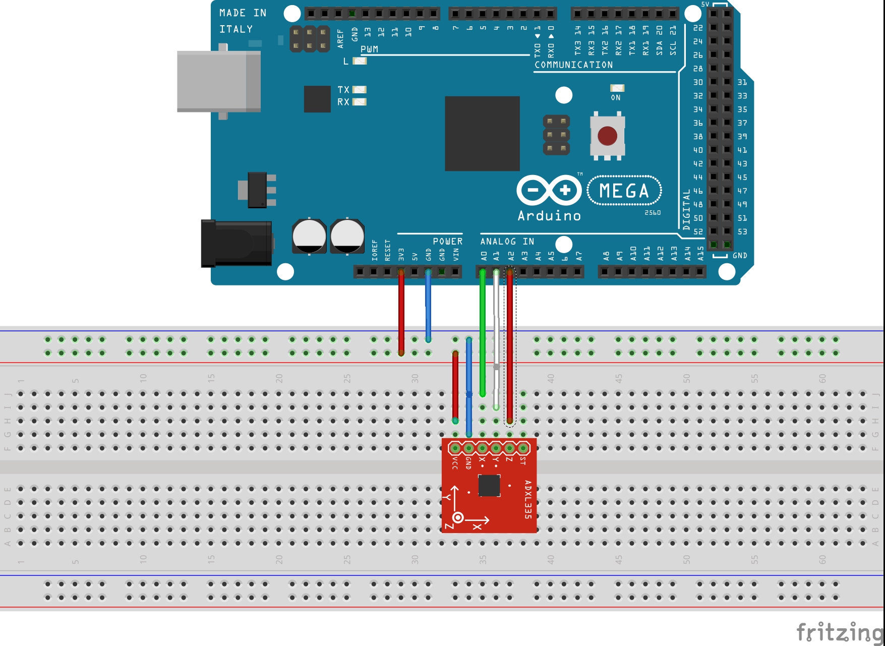
The connections are simple. The sensor provides three analog voltages values proportional to the accelerations along each axis.
- Vcc -> 3V
- Gnd -> Gnd
- A0 -> X
- A1 -> Y
- A2 -> Z
Basic Arduino code
Output
When you upload the code, you will get the raw values from the sensor.
Ready!
      X: 334 | Y: 264 | Z: 344
      X: 334 | Y: 263 | Z: 345
      X: 334 | Y: 264 | Z: 344
      X: 333 | Y: 264 | Z: 344
      X: 333 | Y: 263 | Z: 344
      X: 334 | Y: 264 | Z: 344
      X: 333 | Y: 264 | Z: 344
      X: 333 | Y: 264 | Z: 344
      X: 334 | Y: 263 | Z: 344
These values are proportional to the acceleration along the three axis. Check out the next section to convert the raw data to real acceleration data!