

In this post we will see the results of the implementation of a Real Time system on a Raspberry Pi using Xenomai and linux kernel.
Real-time systems are computing systems that must react within precise time constraints to events in the environment. Embedded and Real Time Operative Systems (RTOS) play a crucial role in our society since an increasing number of applications rely in strict timing constraints. The main characteristic that distinguishes a real-time task from other types of computation is time. The correctness of the system depends not only on the logical result of the computation but also on the time at which the results are produced.
Table of Content
- In the first section we will describe the basic steps required for the implementation of an Embedded System, based on kernel 3.8.13, using the commercial Raspberry Pi model B+ board. The development process will be handled by Buildroot which simplifies and automates the process of building a complete and bootable Linux environment for embedded systems.
Please refer to the following guide to implement it. - We will prepare, in the second section, the linux tree in order to include the Xenomai support provided by the interrupt pipeline.
Please refer to this past article for further information. - In the last section, we will measure latencies with a benchmark tool provided with Xenomai test suite, create a module to handle interrupts on a GPIO port and create a pwm signal with variable period. Tests were conducted with the maximum system load for two hours. Results show that the maximum latency of the system never exceeds 20μs.
As we can see in the graph below, The worst case latency with the Panda board is about 28 μs. We would like to knows the interrupt average and maximum response time for the Raspberry Pi.

Worst case latency with the Panda board is about 28 μs.
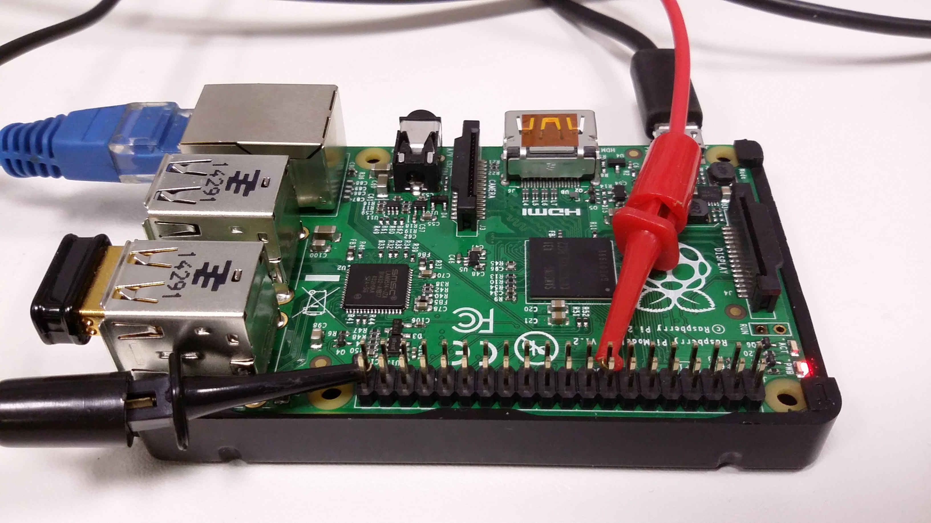
We will create a kernel module in order to register an interrupt and associate an ISR to it to toggle the value of a GPIO pin. We will then measure the system’s response time. The init function requests two GPIO pins, configures one as input and the other as output and registers the interrupt handler. The exit function releases the GPIO pins and the interrupt handler. Here is the response time with 100% cpu usage.

Response time with 100% cpu usage
If you want to know more or implement it with your own Raspberry Pi, check the report!.

![Linux Utilities and Commands 1.20 – [Quick]](http://www.userk.co.uk/wp-content/uploads/2017/03/linux-500x383.jpg)
