

In the last step we’ve set up the Xbee module with the Router configuration, we are ready to wire all up and get started to communicate with the modules.
Wiring
Serial communication is possible thanks to the integrated circuit universal asynchronous receiver/transmitter, abbreviated UART. With the Arduino library called SoftwareSerial it’s possible to replicate this functionality using software and we can get multiple software serial ports with speeds up to 115200 bps.
From the library page
- If using multiple software serial ports, only one can receive data at a time.
- Not all pins on the Mega and Mega 2560 support change interrupts, so only the following can be used for RX: 10, 11, 12, 13, 14, 15, 50, 51, 52, 53, A8 (62), A9 (63), A10 (64), A11 (65), A12 (66), A13 (67), A14 (68), A15 (69).
- Not all pins on the Leonardo support change interrupts, so only the following can be used for RX: 8, 9, 10, 11, 14 (MISO), 15 (SCK), 16 (MOSI).

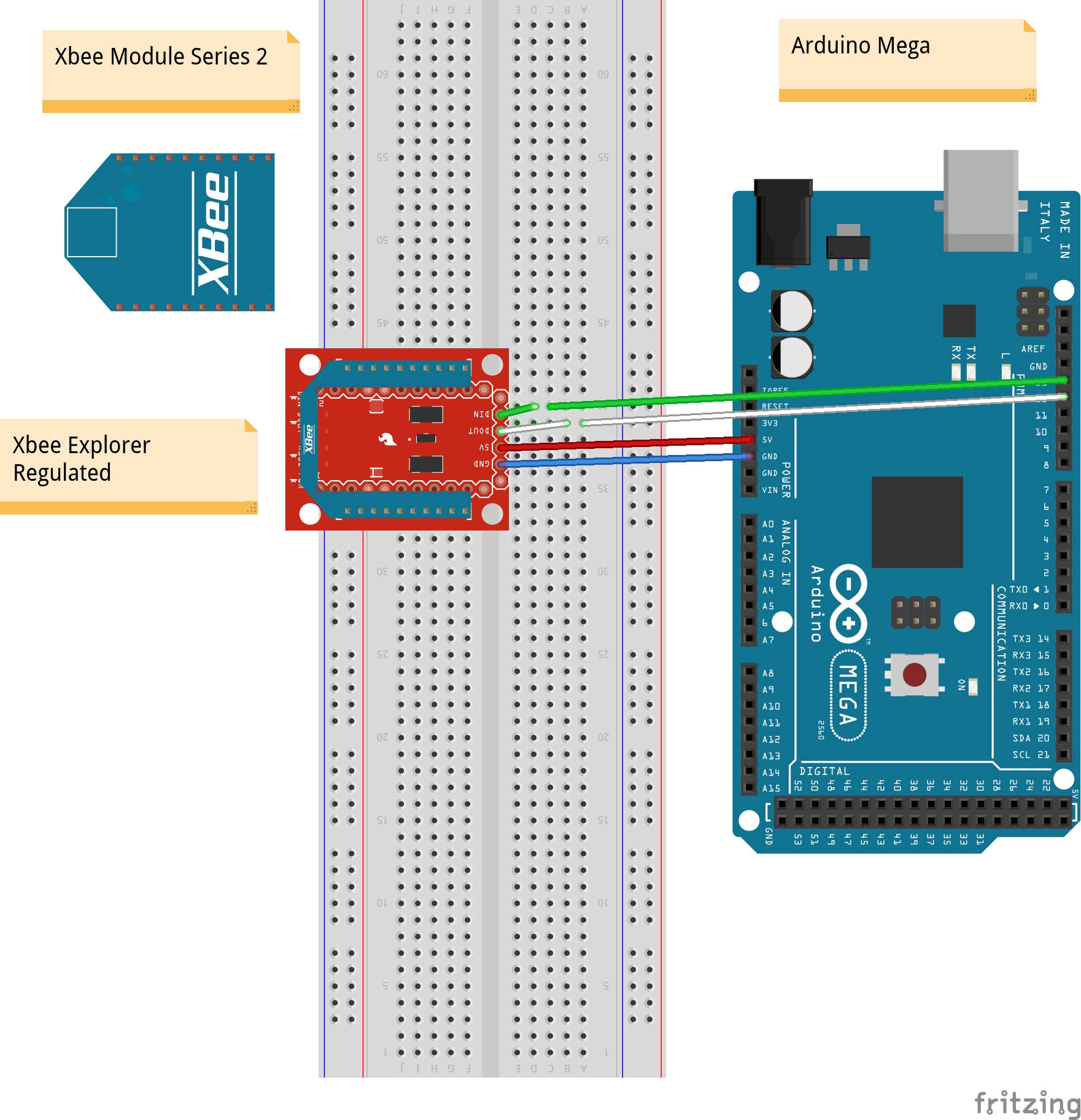
If you have the Mega 2560 version:
Arduino Code
We want to be able to send data we write in the serial monitor, on the Arduino IDE, to the xbee connected to the PC. The same should occur when we type something in the Terminal tab of XC-TU. In order to run a serial communication with the layout of one of the figure above you need to include the SoftwareSerial library. A number of libraries come installed with the IDE, this is one of them so we don’t need to download it.
We will use port 12 and 13 with the Arduino Mega but you can use other ports provided that they support change interrupts and that you make the corresponding changes in the code when you declare the SoftwareSerial object.
SoftwareSerial xbee(pinRX, pinTX);During the Xbee modules configuration we set the baudrate to 9600. We need to declare it with
xbee.begin( BaudRate );Before testing the communication, plug the coordinator into the Xbee Explorer USB socket and connect it to the PC. Open XC-TU, make sure that the module is visible pressing the Test/Query button and go to the Terminal tab. We will write commands to send to Arduino from here.
Then connect the Arduino, with the Xbee Explorer Regulated, to another PC or the same one and run the following code.
/**
 *  Wiring on Arduino UNO
 *  Connect Dout to Pin 2 (Arduino pin(2) Rx , Dout)
 *  Connect Din to Pin 4 (Arduino pin(4) Tx , Din)
 *  Wiring on Arduino Mega
 *  Connect Dout to Pin 12 (Arduino pin(12) Rx , Dout)
 *  Connect Din to Pin 13 (Arduino pin(13) Tx , Din)
 **/

#include <SoftwareSerial.h>

uint8_t pinRx = 12 , pinTx = 13; // the pin on Arduino
long BaudRate = 9600;
char GotChar, getData;

// Xbee SoftwareSerial initialization
SoftwareSerial xbee(pinRx, pinTx); // RX, TX

void setup() {
  Serial.begin(BaudRate);
  Serial.println( "Welcome to the XBee Communication Test" );
  Serial.print("BaudRate:");
  Serial.println(BaudRate);
  Serial.print(" Rx Pin#");
  Serial.println(pinRx,DEC);
  Serial.print(" Tx Pin#");
  Serial.println(pinTx,DEC);
  // set the data rate for the SoftwareSerial port
  xbee.begin( BaudRate );
  xbee.println("Setup Completed!");
}

void loop()
{
  // Reads from serial monitor
  if (Serial.available())
  {
    GotChar = Serial.read();
    // sends char to xbee
    xbee.print(GotChar);
  }

  while(xbee.available())
  {
    getData = xbee.read();

    // sends data back to the Xbee
    xbee.println(getData);

    // prints to serial monitor for visual feedback
    Serial.print(getData);
  }
}
When you open the Serial monitor you should see a “Setup Completed” message in the Terminal of XC-TU. Now type something in the serial monitor and press enter, you should see it in the terminal as well. Try sending something from the computer to the Arduino. The letter you write should appear once in the serial monitor and twice in the terminal. The blu color is for local message and red for remote ones.
Last thing to try is to assemble a long packet with XC-TU terminal pressing the corresponding button on the top right corner and send it to the Arduino. You will notice that the serial communication based on text loses parts of the message.
From the Arduino Cookbook by Michael Margolis:
Sending data as binary bytes is more efficient than sending data as text, but it will only work reliably if the sending and receiving sides agree exactly on the composition of the data.