

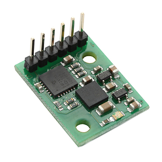
In this post we will use a magnetometer to measure relative angular position with Arduino. We will be using the CMPS10 module which is a tilt compensated compass from Robot Electronics.
This sensor uses a 3-axis magnetometer and a 3-axis accelerometer and a 16-bit processor to measure the x, y and z components of the magnetic field. It requires a power supply at 3.3 – 5v and draws a nominal 25mA of current. We can get roll pith and yaw angles from the module using the serial interface, an I2C interface or a PWM output. It has 0.1 degree of resolution along the z-axis.
For further information please refer to this link.
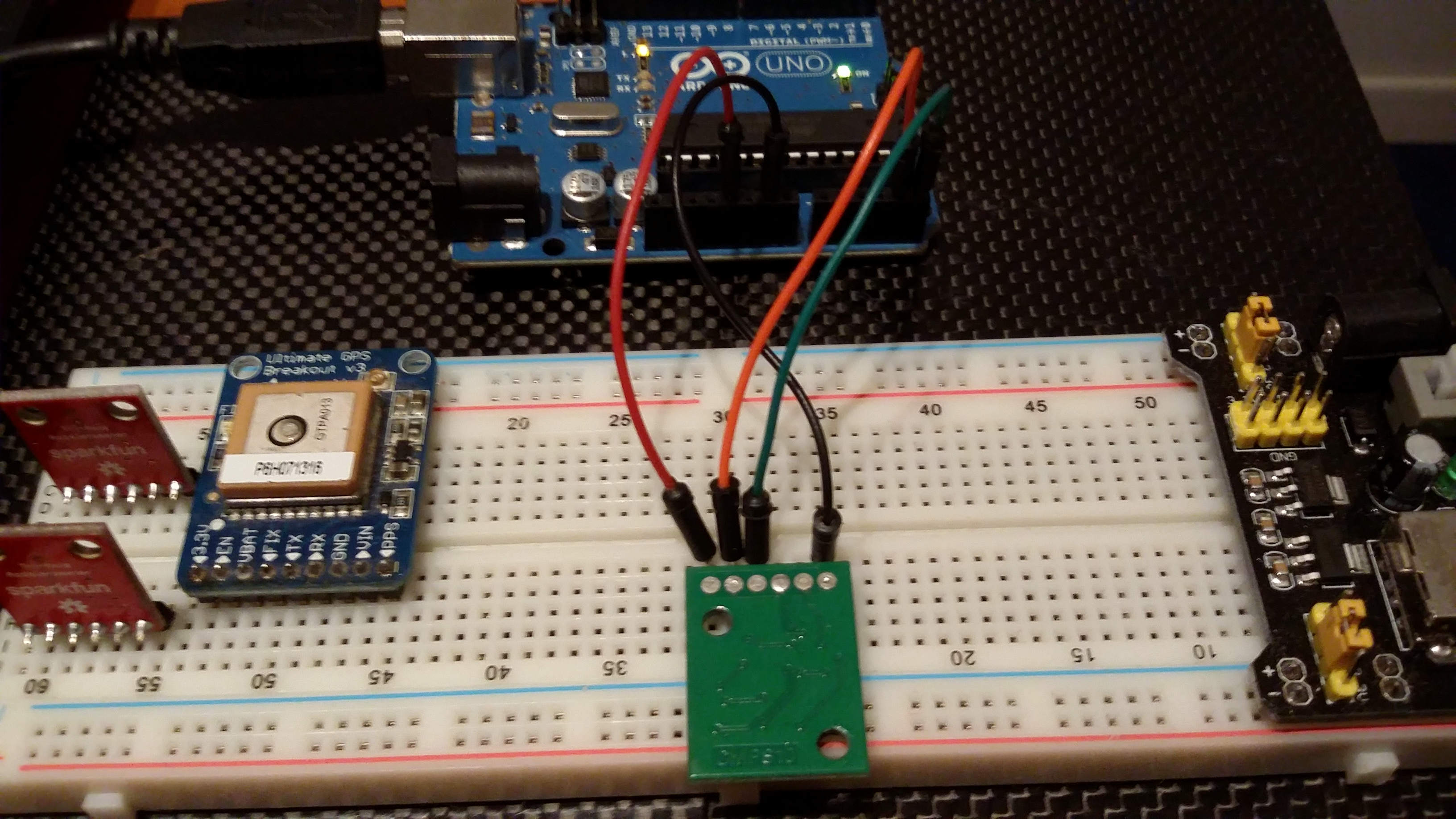
Wiring
We will connect the sensor using the I2C interface to the Arduino Uno. We will refer to this layout.
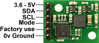
Now if you are using an Arduino Uno, connect SDA to A4 and SCL to A5, if you are using Arduino Mega pins will be pin 20 for SDA and 21 for SCL.
Full code
Upload the following sketch and you will get the relative angular position you were looking for.
Calibration
This calibration could be useful to remove offsets caused by constant magnetic sources around the CMPS10. You need to determine the North and align the CMPS10 with it. Follow these steps to calibrate the sensor. Just make sure that the CMPS10 is not located near to ferrous objects during the calibration process as this will distort the magnetic field and induce errors in the reading.
Factory Reset
Sometimes this module enters in a fault state and the output of the z-axis remains 655.3 even if you unplug the sensor or change voltage input. If this happens you need to restore factory calibration. Use the following function:
Call this function in your setup. Hope this helps!
From the official site:
Restoring Factory Calibration
Should you need to revert to the factory calibration then write the following to the command register in 3 separate transactions with 100ms between each transaction: 0x20,0x2A,0x60. These commands must be sent in the correct sequence to restore the calibration, additionally, No other command may be issued in the middle of the sequence. The sequence must be sent to the command register at location 22, which means 3 separate write transactions on the I2C bus. (A write transaction is
![Matlab Arduino – Setup a serial communication [Quick]](http://www.userk.co.uk/wp-content/uploads/2015/07/Portrait-500x383.png)